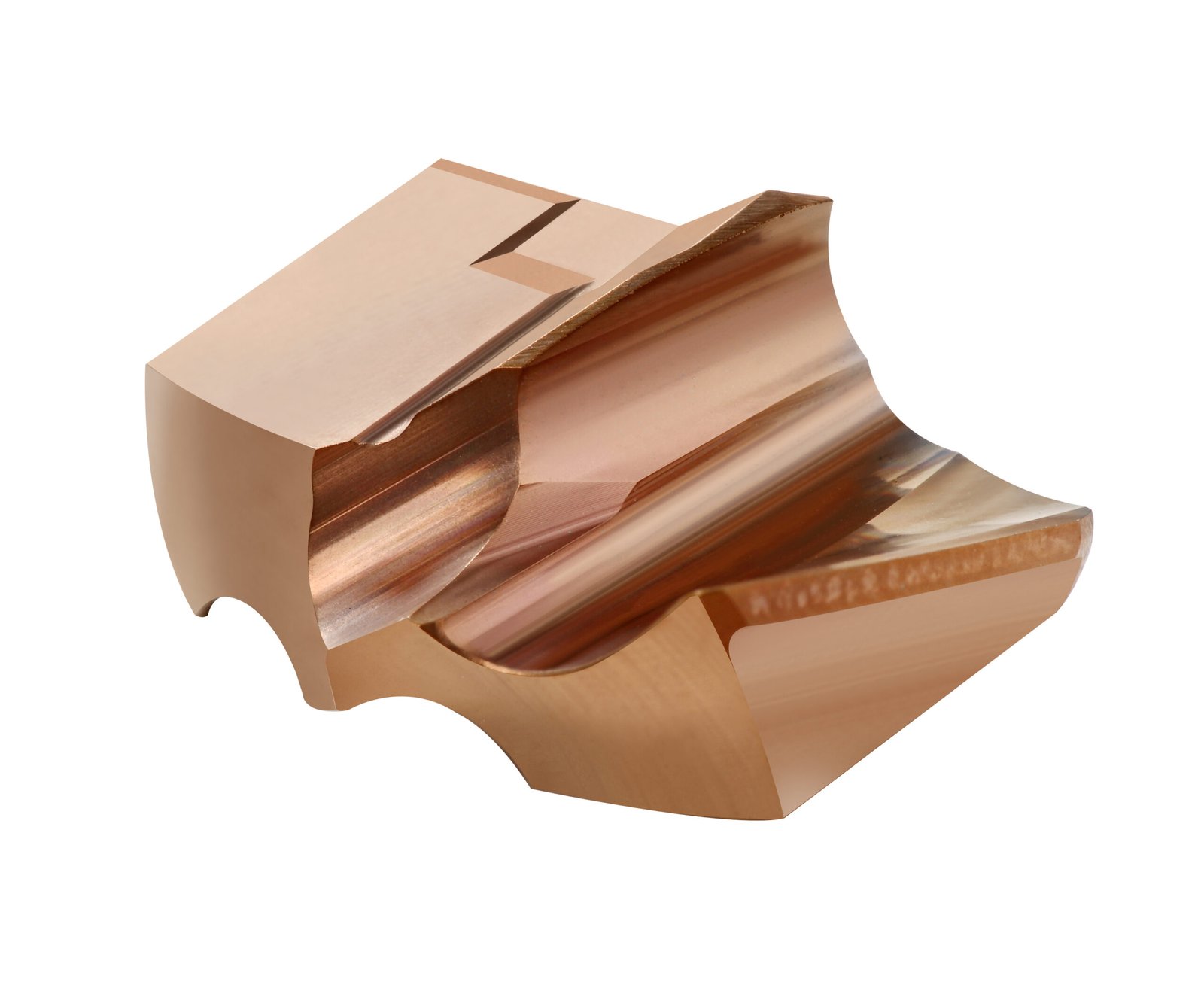

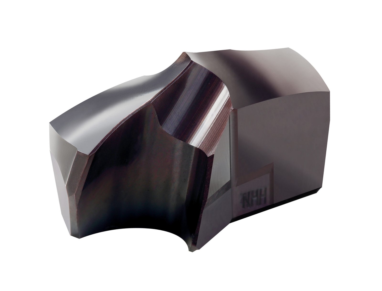
Drill point angle is the included angle at the tip of a drill. It affects the length of the point and the shape of the bottom of a drilled hole. For the same diameter, a larger included angle produces a shorter ideal conical point.
This matters when a drawing specifies a blind hole with a certain depth at full diameter. The drill tip must travel beyond that depth. Knowing the point length helps you check the remaining wall and the space available for the next operation.
Point angle, helix angle and split point are different features
Look at the drill from the side to identify its point angle. The helix angle describes the twist of the flutes along the body. A split point describes a modification around the centre of the tip. These features answer different questions about the tool.
A point angle alone does not describe the rake, relief, edge preparation or chip space. Two drills with the same nominal point angle can have different cutting behaviour and application ranges.
Compare 118°, 135° and 140° using point length
For a simple conical point, the geometry is:
Point length h = D ÷ [2 × tan(θ ÷ 2)]
D is the drill diameter and θ is the included point angle. Use degree mode in the calculation. The table uses a 10 mm drill to isolate the effect of angle.
| Point angle | Point length | Tip depth for 20 mm at full diameter |
|---|---|---|
| 118° | 3.00 mm | 23.00 mm |
| 135° | 2.07 mm | 22.07 mm |
| 140° | 1.82 mm | 21.82 mm |
Haas’s drill-depth reference gives the same rounded point-length factors. These are geometry calculations. Use the actual tool drawing when the tip has a special shape or the remaining wall is critical.
Separate tip depth from full-diameter depth
Imagine a blind hole that must accept a cylindrical feature for 20 mm. If a 10 mm drill is programmed only 20 mm deep to its tip, the conical end occupies some of that depth. The hole will not provide 20 mm at full diameter.
With the ideal 135° point above, a 20 mm tip depth leaves about 17.93 mm at full diameter. To obtain 20 mm at full diameter, the ideal tip reaches 22.07 mm. Keep both dimensions on the setup sheet.
Before using that value, check the distance to the opposite face or nearby passage. Also establish what the machine’s tool-length reference represents. Changing an offset without checking the reference can create a different error.
A tapped hole adds another depth requirement
A tap has an entry lead before it creates a complete thread profile. A blind tapped hole therefore needs room for that lead and the specified clearance below the finished thread.
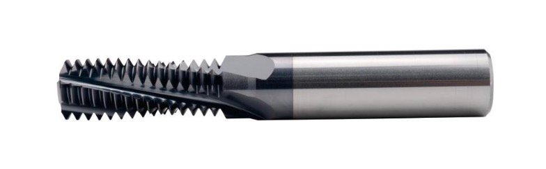
Start with the thread callout, choose the tapping method, and use the tap drill size chart for the diameter reference. Calculate the drilling depth separately using the selected drill and tap drawings. A diameter chart cannot establish the bottom allowance.
The CNC drilling and tapping guide connects these depth checks to the rest of the machining sequence.
Choose geometry for the job, not by angle alone
A comparison such as “118° vs 135°” is useful for understanding shape. It is not enough to select a tool for production. Use the following sequence:
- Identify the workpiece: material grade, condition and hardness.
- Review the hole: diameter, depth, tolerance and required bottom shape.
- Check the entry: flat, angled or interrupted surfaces need suitable tool guidance.
- Choose the cutting geometry: use the selected tool family’s material and application information.
- Check the assembly: holder, reach, coolant route and connection must suit the operation.
For drilling stainless steel, chip formation and evacuation also deserve attention. A change in point angle will not, by itself, establish the correct feed or solve a coolant problem.
What changes when you replace the drill?
A replacement with the same diameter can have a different point length. Compare the drawings before running an existing program. Check the programmed depth, remaining wall, entry method and any later tapping or reaming step.
For a replaceable-head system, record the head model, grade, diameter, body and fastening components. The WVT drill head range provides model information for that comparison. Similar appearance does not establish that two heads fit the same body.
For longer holes, also review the deep hole drilling setup. Point shape is one part of the entry and depth plan.
Common questions
Does a larger point angle make a shallower hole?
It makes the ideal point shorter at the same diameter. The resulting hole depth still depends on the programmed tip position. Use separate dimensions for the tip and the full-diameter section.
Does a split point mean the angle is 135°?
No. Split-point construction and included point angle describe different features. Read the selected tool specification instead of identifying one from the other.
Can a point-angle calculation guarantee bottom clearance?
No. It gives the nominal geometry. The part drawing, actual tool dimensions, datum and setup determine the available clearance.
If the bottom geometry is critical, send Winvera the hole drawing and selected head model. Include the required full-diameter depth and the distance to any nearby wall or passage.