
A tap drill size chart helps you choose the hole before threading. Start with the full thread designation and the tapping method. A cutting tap and a forming tap can make the same nominal thread, but they need different pre-hole diameters.
The chart below covers common ISO metric coarse threads from M3 to M20. It is a reference for tool selection, with all dimensions in millimetres. Production hole limits must come from the selected tap’s application data and the drawing.
Metric coarse tap drill size chart
| Thread | Pitch | Cutting tap | Forming tap |
|---|---|---|---|
| M3 × 0.5 | 0.50 | 2.50 | 2.80 |
| M4 × 0.7 | 0.70 | 3.30 | 3.70 |
| M5 × 0.8 | 0.80 | 4.20 | 4.60 |
| M6 × 1.0 | 1.00 | 5.00 | 5.50 |
| M8 × 1.25 | 1.25 | 6.80 | 7.40 |
| M10 × 1.5 | 1.50 | 8.50 | 9.30 |
| M12 × 1.75 | 1.75 | 10.25 | 11.20 |
| M16 × 2.0 | 2.00 | 14.00 | 15.00 |
| M20 × 2.5 | 2.50 | 17.50 | 18.80 |
Source: selected entries from Thürmer Tools’ metric coarse reference table, checked on 4 November 2026. These are published reference values, not a Winvera test result or a tolerance specification. Fine-pitch, pipe and inch threads are outside this table.
How to read the chart
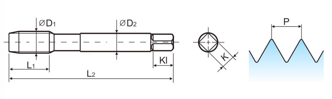
For M10 × 1.5, 10 mm is the nominal thread diameter and 1.5 mm is the pitch. Find both values before selecting a pre-hole. An M10 × 1.0 thread needs a different row; it cannot use the M10 × 1.5 entry simply because both say M10.
Next, select the process column. In this reference, M10 × 1.5 uses 8.50 mm for cutting and 9.30 mm for forming. Those values describe different ways of creating the thread. They are not two interchangeable drill choices for the same tap.
If the process is still undecided, read forming tap vs cutting tap first. Choose the method before ordering the drill.
Can you calculate tap drill size as diameter minus pitch?
For an initial check on many metric cutting-tap applications, the familiar estimate is:
Approximate pre-hole diameter = nominal thread diameter − pitch
For M10 × 1.5, that gives 10 − 1.5 = 8.5 mm. It is a useful way to catch an obvious entry error. It does not establish the permitted hole range or replace the tap’s specification. Do not use this cutting-tap estimate for a forming tap.
Nor does the calculation specify a drill’s manufacturing tolerance. Keep the nominal drill size, the measured hole and the allowable hole limits as separate entries in the setup sheet.
Why do M12 charts show both 10.2 and 10.25 mm?
For M12 × 1.75, diameter minus pitch gives 10.25 mm, which is also the value in the reference table above. An OSG M12 × 1.75 VA-POT product specification instead lists a nominal pre-machined hole diameter of 10.2 mm, together with minimum and maximum hole values.
Do not silently round one manufacturer’s recommendation to match another chart. The two numbers come from different published references. A nominal recommendation and a permitted hole range answer different questions. Follow the specification for the actual tap and thread requirement, then measure what the drilling process produces.
This matters when a shop changes drill supplier or replaces a worn drill. An unchanged label does not prove that the new tool makes the same hole.
Why forming taps need their own hole limits
A forming tap moves material into the thread profile. Its pre-hole controls how much material is available for that movement. A hole that is too small can overload the forming process; an oversized hole can leave an incomplete profile.
Use the forming column only to understand the expected size difference. For a production setup, record the approved minimum and maximum diameter for the selected tap, material and thread. The Gühring threading guide explains why forming-hole selection depends on the workpiece and application.
Set blind-hole depth separately
A diameter chart does not tell you how deep to drill. A blind tapped hole needs room for the required full thread, the tap’s incomplete lead threads and the remaining process clearance. The drill point also extends beyond the full-diameter section of the hole.
Mark these dimensions separately on the setup drawing. Use the drill point angle guide to understand the point allowance. Then select the chip direction using spiral point vs spiral flute taps.
Record the hole before blaming the tap
When a first thread fails inspection, preserve the evidence from the drilling stage. A practical record includes:
- The complete thread callout, including pitch and tolerance class.
- The tap model and whether it cuts or forms.
- The nominal drill size and the measured pre-hole result.
- The full-diameter depth and entry condition.
- The finished-thread inspection result and the method used.
Check the failed feature before changing drill diameter. A size problem, a depth problem and damage caused by trapped chips need different investigations. For stainless parts, the stainless steel tapping guide connects those checks to the material and lubricant.
Choose the tool and pre-hole together
The Winvera threading tool range is the starting point for matching a tap to the job. Include the thread callout, material grade, blind or through-hole condition and usable thread depth in your enquiry. Ask for the matching pre-hole limits with the tool recommendation.
For the complete sequence from the drawing to final inspection, return to the CNC drilling and tapping guide.