
Successful tapping in stainless steel starts with a sound pre-hole, a tap suited to the material and a cycle that keeps rotation and feed coordinated. Then give chips a clear route and deliver the right cutting fluid to the working area. Inspect the first thread before running the batch.
This guide focuses on CNC tapping after drilling. Follow the CNC drilling and tapping guide for the full process, or the separate guide to drilling stainless steel if the pre-hole is still being planned.
Record the grade and the full thread callout
“Stainless steel” does not identify the workpiece closely enough to select cutting data. Record its grade, supply condition and hardness where available. Keep the thread diameter, pitch, tolerance class and usable depth on the same setup sheet.
Also note whether the hole is blind or through. Photograph or sketch any cross-hole, angled surface or fixture that affects entry or chip clearance. This makes an application review more useful than simply reporting that a tap broke.
Inspect the hole before testing another tap
Measure the actual pre-hole rather than relying only on the drill’s marked diameter. Check the usable depth and entry chamfer too. A blind hole must provide room for the tap lead as well as the required full thread.
Review drill condition if the hole surface or cutting behaviour has changed. Sandvik Coromant’s tapping guidance identifies pre-hole preparation, work hardening, clamping and cutting fluid as important parts of the operation. A tapping problem may begin in the drilling stage.
Use the tap drill size chart to identify the appropriate reference for a cutting or forming tap. These methods use different pre-holes. Verify the selected tap’s hole limits before changing the drill to reduce tapping load.
Match the tap to the material and chip route
| Situation | Selection question |
|---|---|
| Through-hole | Can chips and the tap lead pass freely beyond the exit? |
| Blind hole | How will chips leave, and how much space remains below the usable thread? |
| Long chips around the tap | Does the cutting geometry suit the stainless grade and hole form? |
| Considering forming | Is the material suitable, and can the process hold the specified pre-hole and lubrication conditions? |
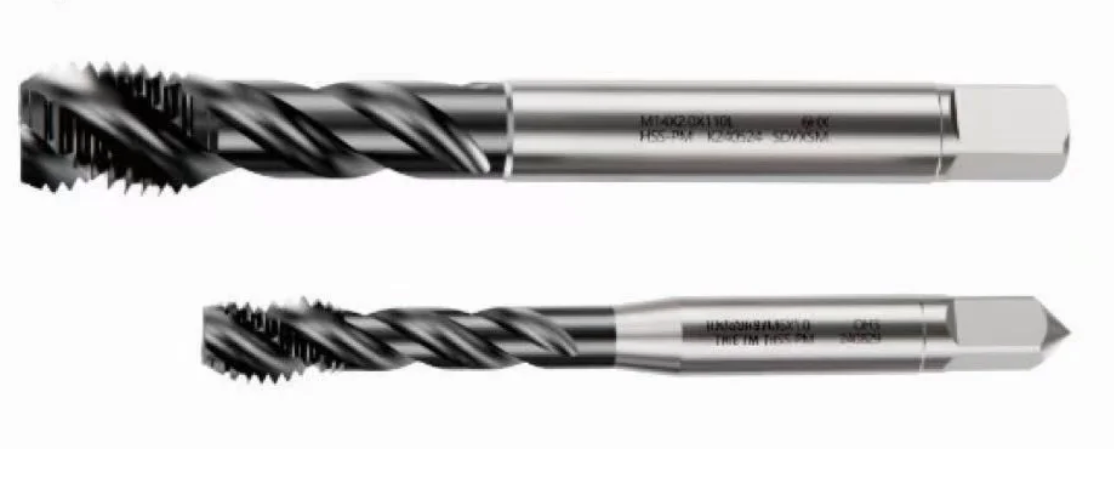
A spiral point cutting tap directs chips forward. A spiral flute cutting tap carries them back towards the entry. The detailed comparison of spiral point and spiral flute taps explains how that affects tool choice.
Winvera lists WTP-POT spiral point taps and WTP-SFT spiral flute taps. Select an exact tool specification for the job, including its application range and lead. A family name alone does not specify a cutting speed or a coating.
If chips are a persistent constraint, evaluate forming versus cutting. Forming changes the process; it is not a direct replacement for a cutting tap in an unchanged hole.
Keep spindle speed and tapping feed coordinated
In rigid tapping, the machine synchronises spindle rotation and axial movement. Haas describes this synchronisation in its rigid tapping reference. Check the cycle and holder instructions for the machine in use.
For a single-start metric thread, the axial advance in one spindle revolution equals the pitch. Where the cycle uses feed in mm/min:
Feed rate = spindle speed × thread pitch
For example, a 1.5 mm pitch at an assumed 400 rpm corresponds to 600 mm/min. This arithmetic example explains the relationship; 400 rpm is not a recommended stainless steel setting. Choose the speed from the actual tap and material data.
Some cycles take pitch or feed per revolution instead. Verify the units and cycle definition before entering F. Do not adjust tapping feed independently as though it were an ordinary drilling feed. Floating holders also have their own setup instructions.
Check cutting fluid at the tool
Record fluid type, measured concentration where relevant and how the fluid reaches the tap. A wet workpiece does not necessarily show adequate delivery inside the hole.
Check nozzle aim or the internal coolant route as appropriate. Use the fluid supplier’s mixing instructions and the tap’s application guidance. Keep these details in the trial record so the next batch can use the same setup.
Diagnose a failure by its stage
After stopping the machine safely, record when the problem occurred. The checks below are a way to organise evidence; the timing alone does not prove the cause.
| Observation | First checks | Useful evidence |
|---|---|---|
| Damage as the tap enters | Alignment, entry chamfer, pre-hole and tool condition. | Entry photograph, measured hole diameter and tool runout record. |
| Load rises near the bottom | Usable hole depth, tap lead, programmed endpoint and chip space. | Drawing depth reference, tap dimensions and the depth where load changes. |
| Breakage during reversal | Cycle synchronisation, holder behaviour, trapped chips and damaged edges. | Program revision, holder type and photographs of the recovered tool. |
| Rough or torn thread surface | Pre-hole surface, cutting edge, fluid delivery and material identity. | Thread photographs and results from a first-piece comparison. |
| Thread fails its gauge check | Correct gauge and thread callout, cleanliness, tap identity and actual hole size. | GO/NO-GO observations and the specified inspection procedure. |
Change one relevant factor at a time and repeat the inspection. If you change the tap, drill, lubricant and program together, the next successful part will not show which change solved the problem.
Separate thread fit from thread depth
A gauge result answers only the requirements covered by that gauge and method. Keep usable thread depth, hole position and other drawing requirements in the inspection plan. Clean the part before inspection and record where a gauge stops.
For a blind hole, compare the required full-thread depth with the tap lead and full-diameter pre-hole depth. Programming deeper without checking the remaining material and tool envelope can create another problem.
Make the next trial repeatable
Save the material identification, tap code, drill code, measured pre-hole, holder, fluid details, cycle revision and inspection result together. Add the number of acceptable threads when you are evaluating tool life. A photograph of a good thread alone does not establish a service-life claim.
If the setup cannot meet the requirement reliably, compare thread milling and tapping before committing to another tool. For a focused review, send Winvera the application details and the evidence from the failed operation.