
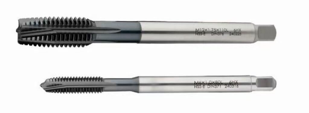
Start with chip direction. A spiral point tap pushes chips ahead of the cutting action, so it is commonly used in through-holes. A typical right-hand spiral flute tap draws chips towards the entry, making it a common choice for blind holes.
The hole label is only the first check. The tap lead, material and available space must fit the operation too. This comparison explains how to make that choice within the CNC drilling and tapping process.
Compare the chip paths
| Feature | Spiral point tap | Spiral flute tap |
|---|---|---|
| Main chip movement | Forward, ahead of the tap. | Back towards the hole entry with the usual right-hand spiral design. |
| Common application | Through-hole with a clear exit. | Blind hole where chips must return through the entry. |
| Space to inspect | Beyond the far side of the workpiece and around the fixture. | Below the required thread and along the return path. |
| What the name does not establish | Material range, lead length or available chip clearance. | Material range, maximum depth or a universal helix angle. |
Tapmatic’s geometry guide describes these chip directions and distinguishes different flute designs. Special geometries exist, so use the exact tap specification when the application differs from the common cases above.
Spiral point taps: check what is beyond the hole
A spiral point is a cutting feature at the front of the tap. The body can have largely straight flutes; the word “spiral” does not mean that its flutes must wrap around the tool like a spiral flute tap.
For a through-hole, chips travel ahead into the space beyond the workpiece. Check that space with the part mounted. A fixture plate, support block or nearby wall can obstruct an exit that looks open on the component drawing.
The lead must also pass far enough to create the required full thread. Reaching the far face with the tip is not the same as cutting a complete thread to that face. Check the actual lead length and programmed end position together.
Spiral flute taps: check the return path and the bottom
A blind hole cannot discharge chips through its bottom. The usual spiral flute selection brings chips back along the tap towards the entry. The Sandvik CoroTap 300 range, for example, is designed for blind-hole applications.
The path back to the surface still needs to remain clear. Record whether chips collect around the shank, holder or hole mouth during the trial. A chip pile at the entry is useful evidence even if the finished thread initially passes inspection.
At the bottom, leave room for the tap’s incomplete lead threads and the required clearance. Use full-diameter drilled depth when checking this space. The pointed end of a drilled hole cannot provide a full-diameter opening for the tap.
Three application examples
The following examples illustrate selection decisions; they are not Winvera machining trials.
A clear through-hole in a plate
The required thread runs through the plate, and the fixture leaves the exit open. A spiral point tap is a candidate. Check that the selected model suits the material, and include both the lead and outgoing chips in the clearance review.
A blind thread in a solid block
The drawing specifies a finished thread depth with material remaining below it. A spiral flute tap is a candidate when chips must leave through the entry. Select the lead geometry, then establish the drilled depth needed to create the full thread.
A through-hole above a fixture plate
The component has a through-hole, but the mounted setup leaves little space beneath it. Treat the obstruction as part of the application. Resolve exit clearance before selecting a tap or cycle. Calling the feature a through-hole does not remove the fixture from the chip path.
Choose the pre-hole and tap lead separately
Both spiral point and spiral flute taps cut threads. Use cutting-tap data for the exact diameter and pitch in the tap drill size chart. Then establish the allowed pre-hole limits for the selected tool.
Lead length is a separate feature from flute style. A short lead can help where bottom space is limited, but it is not a substitute for adequate drilled depth. A “bottoming” description concerns the lead; it does not tell you the chip direction by itself.
Check the depth drawing alongside the drill point geometry guide. This prevents the tapping setup from using the drill-tip depth as though it were all usable cylindrical hole.
Material and coolant still matter
Two taps with the same flute style can have different geometry, coating and application limits. Read the material recommendation for the full order code. Do not choose every stainless application from a general “blind-hole tap” description.
For stainless parts, connect tap choice with the material condition, pre-hole result and lubricant. The stainless steel tapping guide provides the next checks.
When chip problems remain
Stop and inspect the setup before changing several variables. Record where the chips collected and when the problem occurred: entry, full-depth cutting or reversal. Keep a photograph of the chips and tool condition with the original settings.
Compare that evidence with the expected chip path. Check the pre-hole, actual end depth, coolant delivery and selected tap geometry. A problem at reversal may need a different investigation from chips obstructed by a fixture.
If chip handling remains difficult, evaluate another process. Forming taps create the thread without cutting chips where the material and setup support forming. Thread milling offers another route when the machine and tool access permit it.
Match the Winvera series to the application
Review WTP-POT spiral point taps for the through-hole selection path and WTP-SFT spiral flute taps for the blind-hole path.
Send the complete thread callout, material grade and usable thread depth with your enquiry. Add a section view and fixture clearance where the chip path is restricted. These details make the tool choice much more useful than a request based only on nominal thread size.