
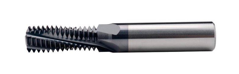
Thread milling makes a thread with a rotating cutter following a helical path. The cutter profile, path diameter and axial movement work together to generate the required thread. A successful setup starts with the complete thread callout and the actual cutter drawing.
If you are still choosing the process, compare thread milling versus tapping. The CNC drilling and tapping guide connects either choice to hole preparation and inspection.
Understand the two rotations
The spindle turns the cutter about its own axis. At the same time, the machine moves the cutter around the thread axis. Spindle revolutions and revolutions of the toolpath are different motions.
For a typical single-start thread, one complete turn of the helical path changes the axial position by one pitch. A 1.5 mm pitch therefore means 1.5 mm of axial change per path revolution. It does not mean 1.5 mm of feed for each spindle revolution.
CMZ explains the use of helical interpolation for thread milling on its machines. Check your control’s required axes and programming method; a machining centre and a lathe with live tooling may generate the motion differently.
Read the thread callout before selecting a cutter
Record the thread standard, nominal diameter, pitch, handedness, tolerance class and usable thread length. Identify whether the thread is internal or external, straight or tapered, blind or through. This guide focuses on the usual setup questions for straight internal threads.
Also record the workpiece material, hardness and any coating or finishing requirement. These details affect the tool and inspection plan even when the nominal thread size stays the same.
Compare six dimensions on the tool drawing
| Feature | Why it matters |
|---|---|
| Cutting profile | It must suit the thread form and the tool’s stated pitch range. |
| Cutter diameter | It must fit the pre-hole and leave room for the required path. |
| Cutting length | It affects how much of the thread can be generated by the chosen strategy. |
| Neck diameter and length | They determine clearance along the hole wall at depth. |
| Shank and holder | They must clear the component, fixture and hole entrance. |
| Overall reach | It must allow access without unnecessary overhang. |
Winvera lists single-thread, three-thread and full-thread milling cutters. Use the individual drawing and order code to determine which tool fits.
The number of flutes around the cutter is different from the number of thread-form teeth along its length. Do not infer either feature from an abbreviated product name. Likewise, a cutter that covers several thread diameters may still have a limited pitch range.
Plan the pre-hole and bottom clearance
Set the pre-hole diameter and depth from the thread specification and cutter guidance. Measure the actual hole after drilling. Inspect the entry and remove loose chips before starting the threading operation.
For a blind hole, draw the tool at its deepest position. Include the cutting tip, neck, shank and holder. Then check the complete entry and exit path. A cutter that reaches the bottom in a static drawing may still collide during an arc.
Keep tip depth, full-diameter hole depth and usable thread depth separate. The drill point angle guide explains why these depth references differ.
Build the toolpath in a clear sequence
- Define the thread. Enter the standard, diameter, pitch, direction and required axial limits.
- Define the actual tool. Use its measured or specified diameter and the relevant cutting profile.
- Choose the strategy. Set entry, helical cutting, exit and any additional passes for the tool and material.
- Check compensation. Identify whether CAM or the control applies the size correction.
- Review the whole assembly. Simulate the tool, holder, part and fixture at the working depth.
- Run and inspect a first piece. Record any changes before releasing the batch.
A program from a similar part can be a reference, but compare its units, work offset, tool dimensions and control conventions before reuse. A different cutter diameter changes the relationship between the thread and the tool-centre path.
Distinguish cutting-edge feed from tool-centre feed
On an internal circular path, the cutter centre travels a smaller circle than the contact point on the thread wall. This is why a straight-line milling feed cannot always be copied directly into the thread-milling cycle.
Sandvik Coromant’s threading application guide distinguishes peripheral feed from tool-centre feed. For its internal-thread calculation, the centre-feed conversion is:
Tool-centre feed = peripheral feed × (Dm − Dc) ÷ Dm
Here, Dm is the machined thread diameter and Dc is the cutting diameter used by the supplier’s calculation. Use that method’s diameter definitions; do not substitute the pre-hole diameter.
As an arithmetic illustration, Dm = 20 mm and Dc = 10 mm give a factor of 0.5. A peripheral feed of 200 mm/min then converts to 100 mm/min at the centre. These assumed values explain the conversion; they do not specify a Winvera cutter or an approved machining feed.
Check whether your CAM system has already made this conversion. Applying it a second time changes the intended feed. Entry arcs and other path segments may require their own treatment.
Inspect before adjusting the diameter
Start with the inspection method and gauges required by the drawing. Record thread fit, usable depth and any other specified features. Keep the first result with the cutter identity and program revision.
If a size correction is needed, first check the tool dimension and compensation method. Follow the control’s conventions for the direction and amount of change. Confirm the result with another inspection rather than assuming the offset value equals the change at the thread.
If the surface becomes rough or results vary, inspect tool wear, runout, pre-hole quality and setup stability. Repeatedly changing the size offset can hide a process problem without solving it.
Prepare a useful thread-milling enquiry
Send the thread drawing, material and hardness, pre-hole dimensions, required reach and machine/control details. Include the cutter code if one is already selected. A sketch showing nearby walls and fixtures is useful when access is limited.
For repeat work, save the proven setup and inspection record. If tapping remains a possible alternative, review forming and cutting taps alongside the process comparison. Ask Winvera to review the thread-milling application using the full part requirements.