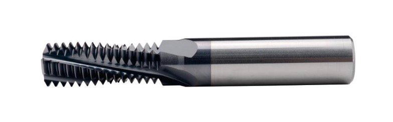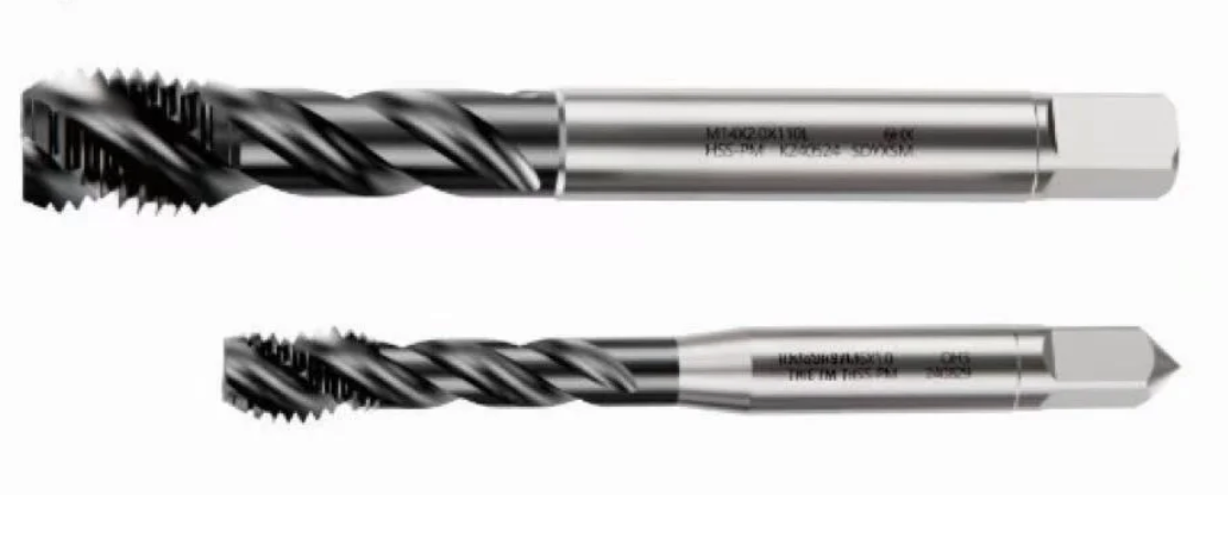

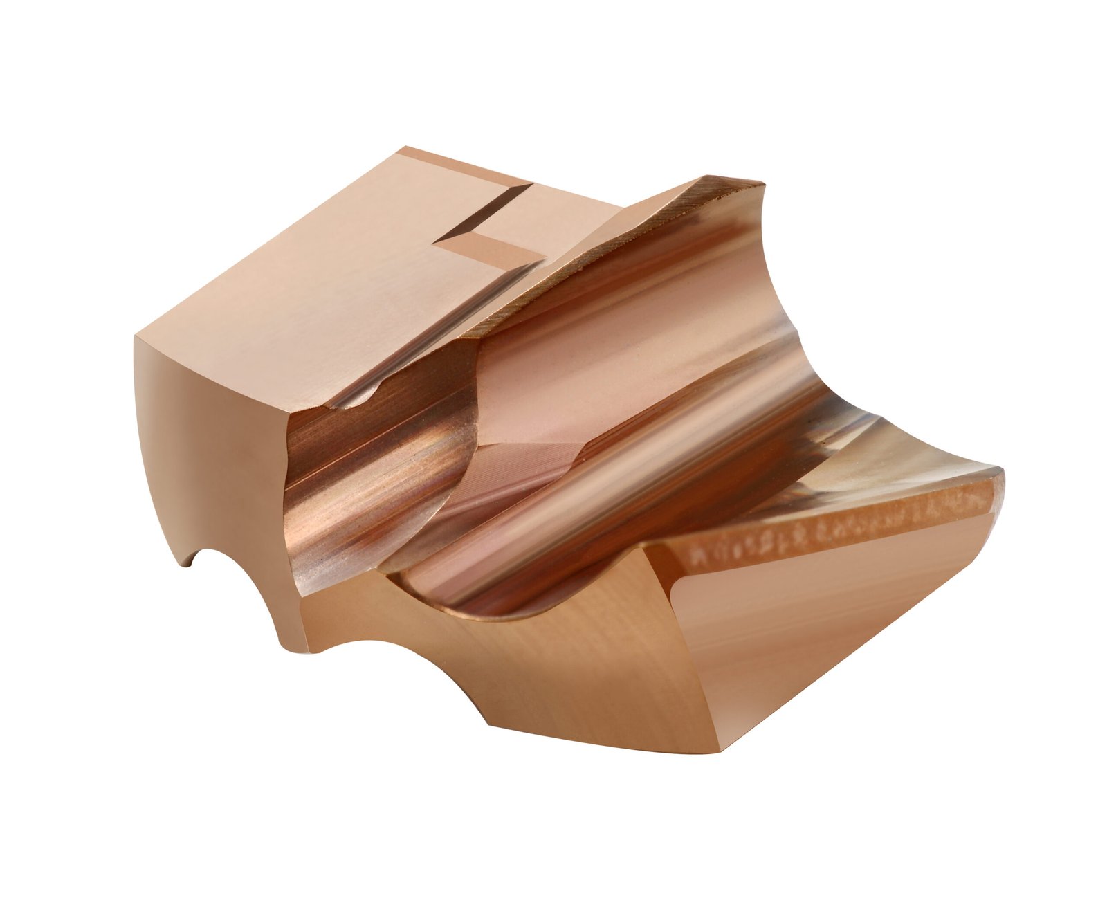
To drill stainless steel well, match the drill to the material, keep the setup rigid and give chips a clear way out. Use cutting data for the exact tool and hole depth. Then check the first hole before running the batch.
For the complete workflow, see the CNC drilling and tapping guide.
This guide covers CNC drilling with a focus on replaceable-head drills. It explains what to check, how to spot trouble and where to start when a hole goes wrong.
1. Identify the material and hole requirements
Start with the material grade and its condition. A job described only as “stainless steel” leaves too much open. Record the hardness if it is available.
Read the drawing for four details:
- Diameter and tolerance: Is drilling the final operation, or will boring or reaming follow?
- Usable depth: How much full-diameter hole does the part need?
- Hole form: Is it a blind hole or a through-hole?
- Entry and exit: Are the surfaces flat, angled or interrupted by another feature?
In a blind hole, the drill tip reaches beyond the full-diameter section. Allow for that point length when checking depth. If the hole will be tapped, also leave the space required by the chosen tap and thread depth.
2. Choose a drill for the job
Drill bits for stainless steel are not all the same. High-speed steel (HSS) drills can drill stainless steel, as the British Stainless Steel Association explains. A carbide or replaceable-head tool needs its own cutting data and setup. Do not transfer an HSS speed or drilling cycle to it without checking the tool guidance.
For a replaceable-head drill, make three checks:
- Cutting head: Match its geometry and grade to the workpiece.
- Drill body: Select the reach needed for the hole and fixture.
- Connection: Match the head, body and fastener as a complete assembly.
Drill point angle alone does not decide whether a head suits stainless steel. The cutting edge and chip-forming geometry also matter. Check the full tool specification rather than choosing only by an angle or coating name.
Before use, clean and inspect the head seat. Install the head with the specified fastener and tightening procedure. Check tool runout and secure the workpiece before starting the cut.
3. Set speed and feed as a pair
There is no single correct RPM for drilling stainless steel. Start with the supplier’s cutting speed and feed for your tool, material and hole depth.
- Cutting speed, Vc: usually given in metres per minute.
- Feed per revolution, fn: the distance the drill advances in one turn, given in mm/rev.
Use the drill diameter to convert cutting speed to spindle speed. Then calculate the linear feed rate:
- RPM: n = (1,000 × Vc) ÷ (π × D)
- Feed rate in mm/min: Vf = n × fn
D is the drill diameter in millimetres. Use cutting data for your selected head, material and depth as the input to these formulas.
Example: if you halve RPM but leave feed in mm/min unchanged, feed per revolution doubles. Check the machine’s feed mode whenever you change speed.
Austenitic grades such as 304 and 316 can work-harden during cutting. Avoid letting the tool dwell and rub against the material. The BSSA drilling guidance explains why maintaining a suitable cutting feed matters. This does not mean that a higher feed is always better.
4. Get coolant to the cut and chips out of the hole
Look at both chip formation and chip removal. A tool may form chips yet struggle to clear them as the hole gets deeper. Review the deep hole drilling setup when extending the reach.
For austenitic and duplex stainless steel, Sandvik Coromant’s drilling guidance highlights sharp cutting geometry, internal coolant and chip control. It also notes that increasing feed can help break chips in some cases. Any adjustment must stay within the selected tool’s application limits.
Before a trial, check the coolant route through the holder and tool. Confirm the required flow, pressure and fluid condition for that assembly. A pump rating alone does not show what reaches the cutting edge.
During the trial, watch for chips collecting at the hole mouth or wrapping around the tool. After stopping the machine safely, inspect the cutting edge and hole wall. Save chip samples and record the settings so you can compare the next trial.
Should you peck drill stainless steel?
Use the cycle specified for the drill and hole depth. Conventional drills and internally cooled carbide tools may need different approaches. Do not add repeated withdrawals simply because the material is stainless steel. Check the tool’s entry, re-entry and chip-clearing instructions first.
5. Troubleshoot one symptom at a time
Do not change speed, feed and the drilling cycle together. Start with the checks below, then test one change and measure the result.
Long chips collect around the drill
- Check that the selected geometry suits the material.
- Compare the actual feed per revolution with the recommended range.
- Check coolant delivery and the path out of the hole.
Distinguish chips that fail to break from chips that break but remain trapped. That helps separate a chip-formation problem from a removal problem.
The hole is oversize or inconsistent
- Inspect the head seat and connection.
- Measure tool runout and check workholding.
- Look for cutting-edge damage and review the entry surface.
Measure the hole at the depths required by the drawing. A single reading at the entrance can miss a change farther down.
The hole wall is scratched or rough
- Check for trapped chips and edge damage.
- Review setup stability and coolant delivery.
- Compare speed and feed with the tool’s application data.
Chip build-up can damage the wall, as described in the BSSA guidance. Avoid treating every surface defect as a speed problem.
The process fails only at greater depth
Record the depth at which the problem starts. Review tool reach, coolant delivery and the drilling cycle at that point. Do not assume that a longer body can use the same process as a shorter one.
6. Inspect the first hole before running the batch
Check diameter, usable depth, surface condition and entry or exit burrs against the drawing. Inspect the cutting edge too. Record the material, tool models, settings and coolant setup with the result.
For tapping stainless steel, check the pre-hole against the selected threading method. Cutting taps and forming taps have different pre-hole requirements. Choose the next operation from the Winvera threading tool range before finalising the hole preparation.
Application example: drilling a stainless steel tube sheet
The following Winvera application record gives the reported details for through-hole drilling in a stainless steel tube sheet with a 25.33 mm MG drill. The reported hole depth was 90 mm. The machine settings were S750 and F90. S750 gives a spindle speed of 750 rpm; the feed calculations below use F90 as 90 mm/min in feed-per-minute mode.
| Item | Value |
|---|---|
| Workpiece | Stainless steel tube sheet |
| Hole type | Through-hole |
| Drill diameter | 25.33 mm |
| Reported hole depth | 90 mm, through-hole |
| Calculated depth-to-diameter ratio | Approximately 3.55D |
| Spindle speed | 750 rpm |
| Recorded feed command | F90 |
| Linear feed used in the calculation | 90 mm/min, assuming feed-per-minute mode |
| Calculated cutting speed | Approximately 59.7 m/min |
| Calculated feed per revolution | 0.12 mm/rev, if F90 = 90 mm/min |
The cutting speed is calculated as π × 25.33 × 750 ÷ 1,000. With feed-per-minute mode, feed per revolution is 90 ÷ 750. The depth ratio is 90 ÷ 25.33. The ratio describes the reported hole depth, not the full programmed travel including approach and breakthrough. These values describe the reported application; they are not a general starting recommendation for all stainless steel grades or hole depths.
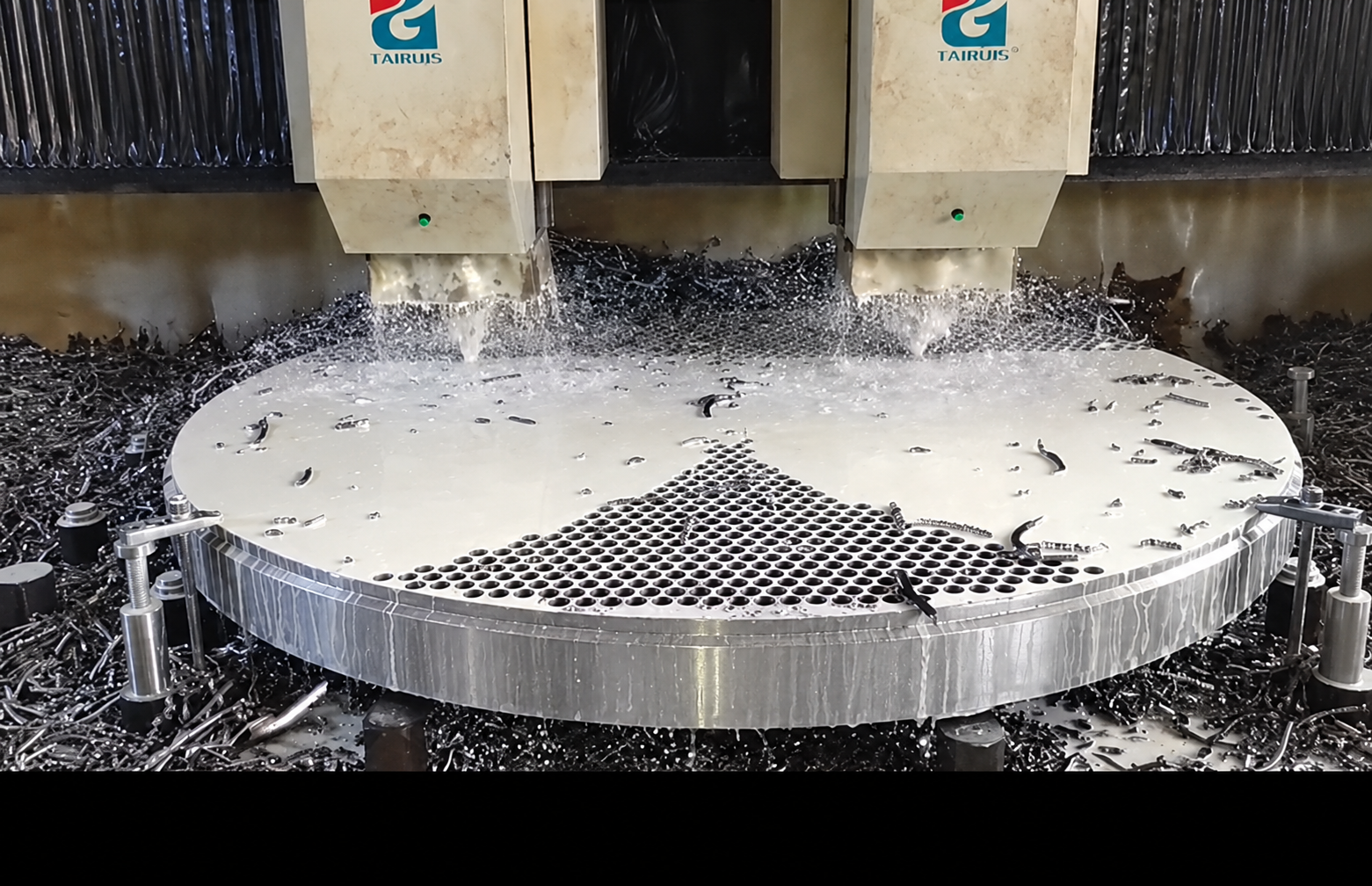
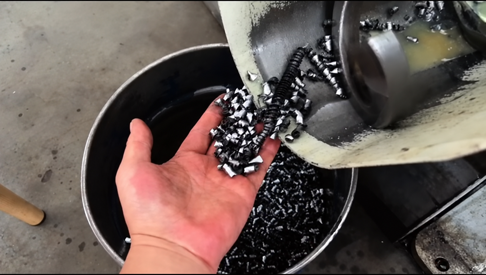
The exact stainless steel grade, feed-mode record and inspection results were not supplied with this example. The photos document the application and the collected chips; they do not establish tool life, hole tolerance or surface roughness.
Choosing a WVT setup for stainless steel
The WVT modular drill system combines a reusable body with a replaceable carbide head. The WVT MG drill head page provides model and grade information for stainless steel applications.
To select a matching assembly, send the material grade, hole diameter, depth and drawing. Add your machine connection and coolant details. If you already use a WVT body, include its full model number.
Ask Winvera to review your drilling application and recommend a matching head and body.