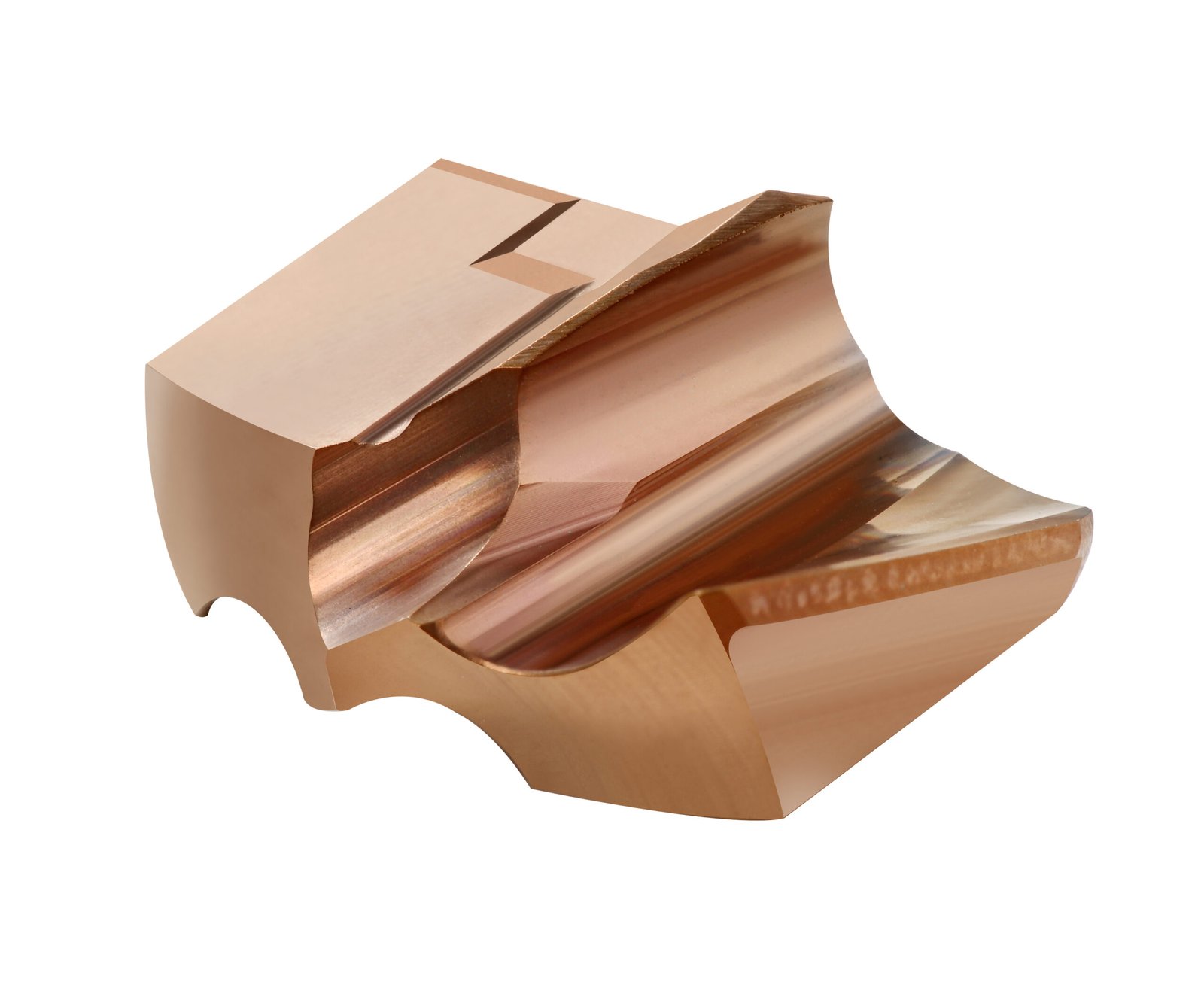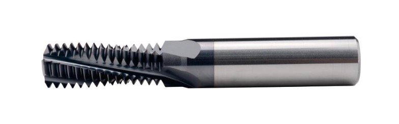

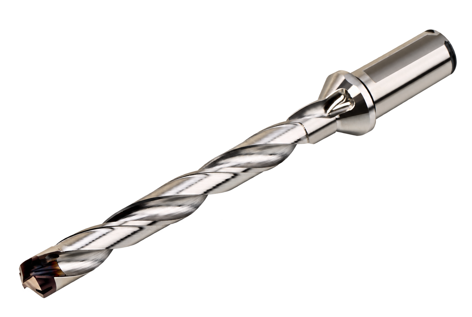
Deep hole drilling puts tool reach, coolant delivery and chip evacuation under the same constraint: the cutting edge works farther inside the part. Selecting a longer drill is only the first step. The entry, cutting cycle and inspection plan must suit the full depth.
This guide focuses on planning a CNC drilling application, including replaceable-head tools. Use it alongside the CNC drilling and tapping process guide.
1. Describe the hole with its depth-to-diameter ratio
Divide the required hole depth by the cutting diameter:
Depth-to-diameter ratio = hole depth ÷ hole diameter
A 20 mm diameter hole with 140 mm of full-diameter depth has a ratio of 7:1, commonly written as 7D. This describes the hole. It does not establish which tool or cycle can produce it.
State the depth reference every time. Depth to the tip, full-diameter depth and total tool reach are different measurements. Reach also includes the space needed to clear fixtures and reach a recessed entry surface.
“Deep hole” does not identify one universal process or a single depth limit. Record the actual dimensions and requirements so a supplier can assess the job without guessing what the label means.
2. Choose the process around the hole specification
List the material, diameter, tolerance, surface requirement, straightness requirement and quantity. Then compare tool families against the machine and coolant available.
| Tool family | What to evaluate |
|---|---|
| Replaceable-head drill | Head/body compatibility, usable reach, head geometry, fastening arrangement and coolant path. |
| Long solid-carbide drill | Supported diameter and depth range, pilot requirements, entry procedure and handling of the long tool. |
| Gun-drilling or another dedicated deep-hole system | Machine suitability, tool guidance, coolant system, chip-return method and inspection requirements. |
A process change may affect much more than the tool purchase. Check machine access, coolant supply and inspection capability before committing to a cycle-time target.
Winvera’s WVT R7, R10 and R12 pages identify 7D, 10D and 12D body groups. Use the exact model dimensions and compatible head specification when assessing an assembly. The depth-group name does not replace a clearance check or qualify the complete process.
3. Plan the entry and exit before setting cutting data
A flat entry face, an angled face and an interrupted surface load a drill differently. Include cross-holes, cast skin and exit geometry on the application drawing.
Where the selected tool requires a pilot hole, record its diameter, depth and bottom shape. Also specify how the long drill enters the pilot, when coolant starts and how the tool changes from entry to cutting speed.
Nachi’s Aqua EX deep-hole guidance, for example, gives a pilot requirement and specific entry and withdrawal limits for that family. This illustrates why a long drill needs a defined sequence. Those values are not WVT operating instructions.
The drill point angle guide explains the difference between tip depth and full-diameter depth. Use the actual tool drawings when matching bottom shapes or checking clearance.
4. Check the complete coolant path
Follow the coolant route from the machine through the spindle or supply connection, holder, drill body and cutting head. Check that the selected assembly supports the required delivery method.
Record the pressure and flow information available for the working setup, together with fluid type, concentration and filtration. A pump’s nameplate rating alone does not describe coolant delivery at the cutting edge.
Coolant and chip evacuation need to be assessed together. Chips may form correctly but remain trapped as the hole gets deeper. For stainless workpieces, review the material-specific advice in drilling stainless steel.
5. Use a drilling cycle intended for the tool
Peck drilling advances in stages with programmed withdrawals. Whether it suits the job depends on the tool, depth, material and chip-clearing method. Adding a peck cycle to every long-hole program can create an unsuitable re-entry sequence.
Record the selected tool’s entry, cutting, breakthrough and withdrawal instructions in the setup. Then check the machine’s cycle definitions: retract distance, feed mode and clearance behaviour can differ between controls.
Review the full tool envelope, including holder and shank. A tool that reaches the bottom can still collide with a clamp or shoulder during entry, withdrawal or a move between holes.
6. Find where the process starts to change
During qualification, record the depth at which a new symptom appears. This is more useful than describing the entire hole as difficult.
| Observation | First checks | Useful record |
|---|---|---|
| Chips accumulate as depth increases | Chip shape, coolant delivery and available exit path. | Depth, chip photographs and the actual speed/feed settings. |
| Damage occurs at entry | Entry surface, pilot conditions, tool seating and runout. | Edge photographs and the stage at which the damage appears. |
| Trouble occurs near breakthrough | Exit geometry, part support and the specified exit sequence. | Exit photographs, burr condition and program segment. |
| Hole size or finish changes along its length | Tool condition, trapped chips and setup stability. | Measurements at defined depths and the inspection method. |
These checks help narrow the investigation; they do not assign a single cause to every symptom. Test one relevant change at a time and compare the next hole with the same inspection method.
7. Plan inspection before producing the batch
Measuring the entrance does not establish diameter or straightness farther down the hole. Choose an inspection method that can reach the required features and resolve the drawing’s tolerance.
Keep the tool models, assembly details, program revision, coolant setup and first-piece results together. If a later hole changes, that record helps distinguish tool wear from a setup or material change.
Send a complete deep-hole drilling enquiry
Provide the material grade and hardness, hole diameter, full-diameter depth, tolerance and quantity. Add entry and exit features, machine connection, available coolant and fixture limits.
If you already have a WVT body, include its complete model and the installed head and fastener. Ask Winvera to review the complete drilling application so the proposal can address the assembly, working reach and process requirements together.