

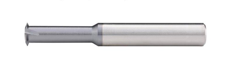
Tapping is often the first process to evaluate for repeated standard internal threads. Thread milling is worth evaluating when you need diameter adjustment, several compatible thread sizes or a different way to manage an expensive part. The right choice depends on the thread, machine, tool access and measured production cost.
This guide compares the two processes before you commit to a tool. For the complete sequence from drilling to inspection, use the CNC drilling and tapping guide.
The main difference is how the tool moves
A tap rotates and advances into the hole to cut or form the thread. Its axial movement follows the thread lead. A thread mill spins while the machine moves it along a helical path. That path and the cutter profile generate the thread together.
With tapping, choose a tap for the required thread designation and fit. With milling, the cutter still has profile, pitch and size limits, but the programmed path gives another way to adjust the finished diameter.
| Question | Tapping | Thread milling |
|---|---|---|
| What machine capability is needed? | A suitable tapping cycle and holder. | The required helical motion, a suitable spindle and a verified toolpath. |
| How is the thread size controlled? | Tap geometry and size, supported by a stable setup. | Cutter geometry plus the programmed path and compensation. |
| Can one tool cover different sizes? | A different thread designation usually needs a different tap. | Some cutters cover several diameters within their specified profile and pitch range. |
| What needs room below a blind thread? | The tap lead and the specified bottom clearance. | The cutter, neck and entry/exit path. |
| What deserves close attention? | Pre-hole size, chip path, lubrication and synchronisation. | Pre-hole size, cutter clearance, path direction, feed and compensation. |
Start with machine capability and access
Eliminate any process that your machine cannot support before comparing tool prices. For tapping, check how the spindle and axial feed stay coordinated. For thread milling, check how the control generates the helix and whether the whole tool assembly clears the part and fixture.
A machining centre and a turning centre may need different axis arrangements for the same thread. CMZ’s helical thread milling guidance illustrates how live tooling and the hole’s position affect the required lathe configuration.
Next, read the full drawing callout: thread standard, diameter, pitch, tolerance class, handedness and usable depth. A note such as “M10” leaves important selection details unresolved. Include whether the thread is blind or through, and whether a later coating affects the finished requirement.
When tapping is a strong starting point
Start by evaluating tapping when a part has many holes with the same standard thread, the machine supports the process and a suitable tap is readily available. A repeat job with a proven tapping setup also provides a useful baseline.
DATRON’s process comparison identifies cycle speed as a potential advantage of tapping on a suitable machine. Measure the complete cycle on your own part, including positioning, reversal and chip handling.
Before the trial, decide between forming taps and cutting taps. This changes material suitability and pre-hole requirements. For a cutting tap, choose a geometry that gives chips a clear route out of the cutting area.
When thread milling deserves a trial
Evaluate thread milling when adjustment of the thread diameter is useful, or when several thread sizes could share a suitable cutter. It may also be worth testing on high-value components where the consequences of a failed tool matter as much as cycle time.
A cutter that fits several diameters does not automatically fit several pitches or thread standards. Check its cutting profile, minimum thread diameter, pitch range and reach. A small cutter also needs enough clearance for its neck and holder at full depth.
The practical next step is the thread milling setup guide. It covers tool drawings, feed calculation and first-piece adjustment. Include the time required to create and verify the program when comparing processes.
Two examples of how to make the choice
A plate with many identical through-threads
Suppose the drawing has a large number of identical M8 × 1.25 through-threads. Begin by checking tapping capability, exit clearance and a tap suitable for the material. Compare the first-piece results and total cycle time against milling only if there is a reason to change the process.
The open exit helps define a possible chip route. It does not guarantee that the fixture leaves enough room for the tap lead and chips. Include that space in the setup review.
A costly housing with several thread diameters
Suppose a housing needs several internal thread diameters. List which share a compatible pitch and profile, then check whether one thread mill actually covers that range. Compare tool changes, programming work, thread adjustment and the value already added to the part.
These are selection examples, not Winvera production trials. The decision comes from the verified tool range and acceptable parts produced in your own setup.
Compare the cost of acceptable parts
Record the same information for each viable process. A tool that costs less to buy may still cost more per accepted part if it needs frequent changes or extra inspection.
| Record | What to include |
|---|---|
| Setup | Programming, tool setting, first-piece inspection and adjustments. |
| Cycle | Positioning, cutting, reversal or withdrawal, and tool changes. |
| Tool use | Actual tool cost and acceptable threads produced before replacement. |
| Quality | Inspection time, rejected parts and any recovery work. |
| Repeat work | Time to restart the same job using the recorded setup. |
For a short run, setup effort may dominate. For a repeat order, small differences per hole can become important. Use the planned quantity and your shop’s actual rates; do not apply a generic savings percentage.
Fix the pre-hole before changing the process
Both routes depend on sound hole preparation. Check diameter, usable depth, position and entry condition. Use the tap drill size chart for the selected tapping method. Establish a thread-milling pre-hole from the thread requirement and cutter guidance.
Switching from a cutting tap to a forming tap or a thread mill requires a new review of that hole. A previous operation’s diameter should not become the new default simply because the nominal thread size stays the same.
Choose the route, then specify the tool
Winvera’s threading tool range includes taps and thread milling cutters. Send the complete thread callout, material and hardness, hole form, usable depth, quantity and machine details. These let the tool selection start with the part requirements.
If milling is already the preferred route, compare the dimensions on the single-thread milling cutter page with the actual hole. Release the process after the first piece meets the drawing and the setup can be repeated.
Pingback: CNC Drilling and Tapping: A Practical Process Guide
Pingback: Thread Milling: Tool Selection and CNC Setup - Winvera Precision tools